
|
Shenzhen KYL Communication Equipment Co., Ltd
|
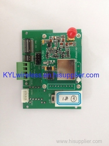
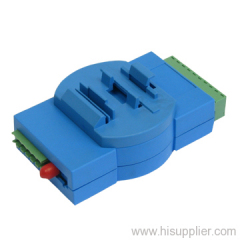
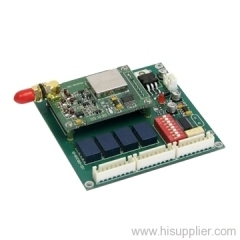
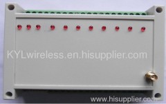
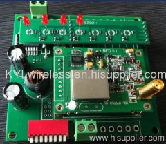
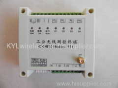
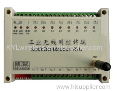
KYL-501 Motor Monitoring Module
| Price: | 50.0 USD |
| Payment Terms: | T/T,WU;Paypal |
| Place of Origin: | Guangdong, China (Mainland) |
|
|
|
| Add to My Favorites | |
| HiSupplier Escrow |
Product Detail
Use for wireless irrigation, vavle control, motor control, ON-OFF control
I. Description
Receive the motor control signal wirelessly.
Drive the motor turn forward or its reversal rotation

Working diagram
II. Technical Specification
1. Maximum driving current: 2A
2. Collocate with standard 500mW data module, transmission distance is 2-3km LOS, frequency 433MHz, receiving sensibility -120dBm.
3. Receiving current: 30mA, transmitting current: 300mA
4. Power supply: D.C. 9V
5. Dimension: 80mm*60mm
III. DIP Switch Definition
1. SW1, channel setting
DIP1-4: Choosing module's channel. Maximum 16 channels
The corresponding channel for DIP1-4
(White part means blank, black part means switch is there, for example, channel 1, DIP 1-4 all ON)
IV. Pin definition
Port name | Pin No. | definition | remarks |
COM1 | 1 | GND | GND |
2 | VCC | DC: 9V | |
3 | NC | ||
4 | NC | ||
COM2 | 1 | M+ | Motor driving positive and negative |
2 | M- | ||
3 | NC | ||
4 | NC |
V. How to use it
1. Set the DIP ready according your using requirement and connect power supply correctly(9V)
2. Power on
3.choosing different channels to avoid interference if you use more than 2 groups in an area.
Related Search
Monitoring System
Alarm Monitoring
Remote Monitoring
Tire Pressure Monitoring System
Lighting Power Monitoring
Tire Pressure Monitoring
More>>
Find more related products in following catalogs on Hisupplier.com
Company Info
Shenzhen KYL Communication Equipment Co., Ltd [China (Mainland)]
Business Type:Manufacturer
City: Shenzhen
Province/State: Guangdong
Country/Region: China (Mainland)
|
Minerva:
|
|
KYL-Minerva:
|
You May Like:

Product (37)
- power amplifer (4)
- Wireless I/O Module (7)
- RF modules (10)
- Mini-size Transceiver (6)
- Radio Modem (3)
- Long Range Radio Modem (2)
- Wireless Audio Modem (5)
